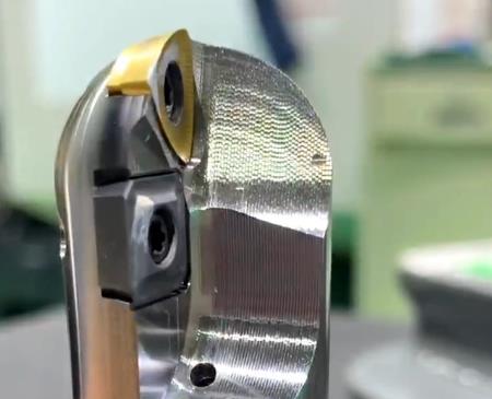
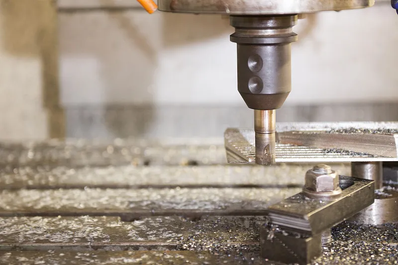
With the rapid development and popularization of CNC technology, a variety of complex, special high-precision parts machining efficiency and process requirements are increasingly stringent, and the accompanying new, special tools are also increasing, this introduces the application of ball-end lathe using the tip of the arc radius compensation function in the CNC lathe machining of arc groove parts methods and techniques.
As shown in Figure 1 parts: blank for 45 # steel, size Φ40 × 82mm, in the CK6140 CNC lathe processing, the requirements to ensure its machining accuracy.
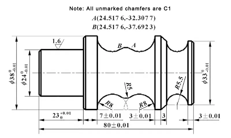
Figure 1 parts diagram
Parts analysis and tool selection
Parts diameter tolerance is 0.01mm, Φ24 length direction tolerance of 0.01mm, the rest of the tolerance is 0.02mm, and surface roughness of Ra1.6. Φ38 left end of the outer circle, with the general cylindrical cutter is very easy to process, the right end of the R5.5, R8 semi-circular arc groove, and the R5 convex arc and other parts of the general cylindrical lathe tool machining is easy to cause interference, resulting in overcutting, so that the parts scrap, difficult to complete the processing. Difficult to complete the processing.
In order to complete the processing task and improve the surface quality of the parts, the choice of radius R4 ball turning tool processing.
Ball turning tool arc radius on the impact of machining accuracy
CNC program is generally for a point on the tool that is the tool point, according to the size of the workpiece contour preparation.
The ball turning tool position point is generally the tip of the arc center point O. In actual processing, the cutting point is not an ideal fixed point, but a section of the arc.
When cutting the tool cutting point in the tip of the arc changes, resulting in the actual cutting point position is different and producing deviation, easily causing overcutting or undercutting.
This is due to the tip of the tool is not an ideal point but a section of the arc, resulting in machining errors, the tip of the arc radius compensation function must be used to eliminate.
Tip radius compensation is through the G41, G42, G40 code, and the T code specified in the tip radius compensation number, to establish or cancel the radius compensation.
G41: left tool compensation, along the tool forward direction, the tool is located in the left side of the workpiece compensation, see Figure 2;
G42: right tool compensation, along the tool forward direction, the tool is located in the right side of the workpiece compensation, see Figure 2;
G40: cancel the tip radius compensation.
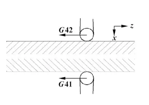
Fig. 2 Schematic diagram of tip radius compensation
Determination of the direction of the tip of the ball-end turning tool
Turning tooltip direction number defines the tool position point and the location of the tip arc center of the relationship, from 0-9 there are 10 directions, combined with Figure 3, 4, turning tool tip orientation for 0 or 9.
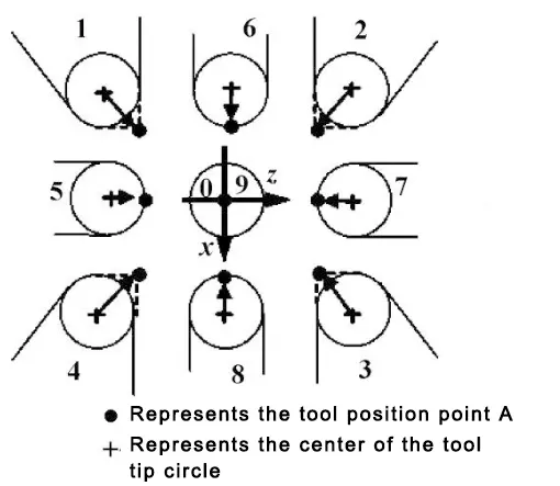
Figure 3 tool tip direction number
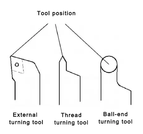
Figure 4 typical turning tool tool position point diagram
Ball turning tool to the tool
Using the test cut method of tool setting, because the ball head turning tool position point in the arc center point O, and programming is programmed with the graphic contour, so the tool should be set to point O for the reference point of the tool, and the program must be added to the tip of the tool radius compensation function, such as the size of the tool as shown in Figure 5 value, in the tool bias table corresponding to the tool number column “test cut length” in the input Trial cut length value “R”; in the “trial cut diameter” column, enter the trial cut diameter value “D + 2 × R”.
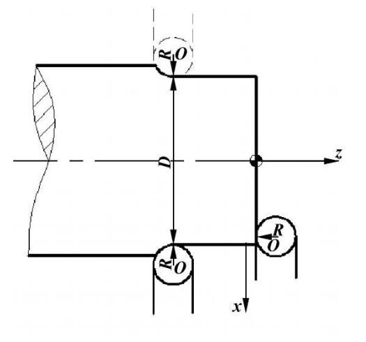
Figure 5 Test cut method of tool setting
Processing program and process sketch
(1) Clamp the right end of the blank first, and machine the Φ24 and Φ8 outer circle of the left end, the machining program and process sketch are sketched;
(2) headset clamping ¢ 24 cylindrical surfaces, process sketch shown in Figure 6, machining the right end of the R5.5, R8 semi-circular arc groove and the convex arc of R5 and other parts, and in order to ensure the machining accuracy, programming the size of the parts to take the middle of the tolerance.

Figure 6 process sketch
%0001
T0101
M03 S600
G00 X56 Z8; X value must be greater than 48, Z must be greater than 4
G71 U0.8 R2 P10 Q20 X0.6 Z0.01 F150
N10 G42 G00X31; create tool patch
S1000
G01 Z0 F100
X32.995 Z-1;
Z-3
g02 x33 w-11 r5.5
G01 X38 W-3
W-3
g02 x24.5176 z-32.3077 r8
g03 x24.5176 z-37.6923 r5
G02 X38 Z50 R8
N20 G01 X56
G40 G00 X100;
Z100
M05
M30
Conclusion
In similar half-arc groove parts processing, the application of a ball-end turning tool and tool tip arc radius compensation function often can play a multiplier effect, otherwise, it will make programming difficult or difficult to ensure the quality of machining, easy to cause overcutting, undercutting and other machining interferences, and at the same time, in the program positioning point selection should be able to ensure that the tool to smoothly establish the tool patch and cancel the tool patch.

