With the continuous development and progress of industrial science and technology, sheet metal chassis have been widely used in the fields of electronic and electrical appliances, communications, automotive industry and medical devices.
To cope with the increasingly severe challenges in industrial manufacturing, sheet metal chassis products are required to have higher performance and reliability and to reduce costs while maintaining quality.
The choice of connection method is crucial to the performance and reliability of the overall structure in the design and manufacture of sheet metal chassis.
Different connection methods involve a variety of factors such as material selection, production process, and cost.
Therefore, in-depth study and comparative analysis of different connection methods are significant.
The research in this paper will conduct a detailed comparative analysis of various connection methods.
This analysis will cover their basic principles, scope of application, advantages and disadvantages, process requirements, and associated costs.
The goal is to provide a comprehensive and in-depth understanding of how to select appropriate connection methods for sheet metal chassis structures.
The results of this study are expected to provide valuable references for engineers, designers, and decision-makers in related fields.
These findings aim to support their work and guide informed choices in practical applications. In addition, the study is intended to promote progress and innovation in sheet metal chassis manufacturing technology.
Comparative Analysis of Multiple Connection Methods for Sheet Metal Chassis Structural Parts
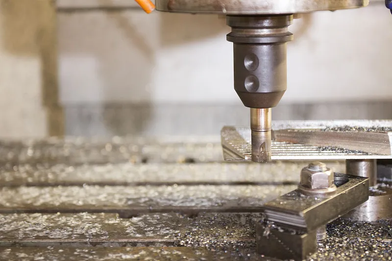
Sheet metal is usually a comprehensive cold working process, including shearing, stamping, bending, splicing, molding, etc., to produce parts of various shapes and sizes.
The distinctive feature of sheet metal is the consistent thickness of the same part.
Based on this, sheet metal structural parts typically have several key characteristics. They are lightweight and have high strength. They also offer high precision and high productivity.
These parts are conductive, making them suitable for electromagnetic shielding. They are also low in cost and perform well in mass production settings.
A sheet metal chassis is a finished product assembled from several structural components through various connection methods.
Along with the wider application of sheet metal structural components, their connection methods are also becoming more diversified.
The more commonly used connection methods mainly include threaded connection, riveting, welding and other major categories.
Further subdividing, threaded connections can be classified into screw connections and bolt connections.
Screw connections are mainly used with riveted parts or by tapping threads directly into the material. In contrast, bolt connections require the use of nuts to secure the joint.
Rivet connections include pull rivet, pressure rivet, turning hole rivet, and nailless rivet connections.
Welding is mainly resistance spot welding, laser welding and argon arc welding.
Through the above connections, many chassis structural components are fixed in the corresponding position, and ultimately, to realize the entire sheet metal chassis assembly of finished products.
Threaded Connection
Threaded connection generally refers to the use of threaded parts or the connected parts through one flexible and removable connection.
Threaded connections are usually categorized into screw connections and bolt connections.
In the case of bolted connections, there is no need to cut threads on the connected parts, and the material of the connected parts is not restricted.
Hence, the construction is simple, and assembling the parts from both sides of the connected parts is generally necessary.
Bolt connections can be connected to different properties of the material.
A wider range can provide a higher connection strength to meet the needs of different application scenarios.
However, in some narrow spaces or complex occasions, the bolt connection may not be easy to install or maintain, and bolts and nuts need to be operated on both ends during the process, which will affect the assembly efficiency to a certain extent.
As shown in Fig. 1, the left side is the state of conventional bolt connection, and the right side is the installation in the flat bottom hole to ensure the flat surface of the structural components.

When screw connection is used, it is necessary to have matching threads on the connected parts.
The more common structural forms on the structural parts of sheet metal chassis are rivet nut/stud, direct tapping/indirect tapping (hole tapping) and so on.
Based on extensive actual production experience, some important observations have been made. Sheet metal chassis structural components are typically manufactured through sheet metal processing.
As a result, their thickness is generally quite thin. If direct tapping is used on such thin material, screw connections may cause a large area of stripped threads. This can eventually lead to thread failure and unreliable connections.
Therefore, higher strength rivet nuts are chosen to solve this problem.
Similarly, it is the thin plate characteristics of sheet metal that allow us to turn the holes before tapping, to increase the number of effective threads to increase the effectiveness of the screw connection.
In contrast to the bolted connection, the screwed connection has a different structure and approach. It is equivalent to having the “bolt” built into the structural member in advance.
This allows screws to be fastened directly during assembly without needing to handle separate bolts. As a result, the operation becomes easier to automate. This significantly improves the efficiency of the assembly process.
In addition to this, bolted connections are more commonly used for medium to large-sized parts. However, in sheet metal chassis products, the parts are generally small in size.
Because of this, screw connections are usually sufficient to meet most usage scenarios. They also provide adequate strength support for these smaller components.
Therefore, screw connections are the more commonly used connection method in this context.
When connecting structural components of sheet metal chassis, the surface condition of the components after installation must also be considered.
Typically, both ends of the bolt connection will protrude from the plane of the structural member, and a flat-bottom countersunk hole is set on the bolt side to realize the surface leveling.
The screw connection can be directly selected countersunk head nails and with the structural components on the countersunk holes to realize.
Still, the other side will also protrude from the plane of the structural elements. The non-protruding state can facilitate the subsequent installation of the chassis into different products.
As shown in Figure 2, respectively, represents the rivets and direct tapping connection, but also shows the surface of the screw after the installation of the protruding state.

Riveting
Riveting is usually a method of joining multiple workpieces together using rivets.
The principle of riveting is that by applying pressure to both ends of the rivet, the end of the rivet expands and forms a tight connection with the workpiece.
The different types of rivets can be divided into pull riveting, pressure riveting, and riveting, with the corresponding being used for pull riveting rivets and pressure riveting rivets.
Pull rivets, also known as blind rivets, are a common type of fastening component. During the riveting process, the rivet core is pulled by a special rivet gun.
This action causes the body of the rivet to expand, creating a secure connection. The expansion of the rivet body serves the purpose of achieving effective riveting.
To perform pull riveting, special tools such as riveting guns must be used. These tools can be manual, electric, or pneumatic. The specific implementation of this process is illustrated in Figure 3.
Pull rivets:
Various rivets in the sheet metal chassis structure can, accordingly, be countersunk holes or plain through-holes.
Different rivets, including double-sided flat, single-sided flat, double-sided raised, and other effects, can be selected according to different conditions of use and specific selection.

Pressure riveting rivets can be divided into hollow rivets and solid rivets, which require pressure riveting equipment.
Hollow rivets are riveted in one way, solid rivets are riveted in another way; the two need to cooperate with different riveting tooling to complete.
Pressure rivets come in a variety of head shapes. These include countersunk heads, round heads, flat heads, and more. They can also achieve different effects after installation.
Examples include double-sided flat, single-sided flat, and double-sided raised finishes. These variations allow pressure rivets to be used in different application scenarios.
The completed state of riveted structural components is shown in Figure 4.

In addition to the above-mentioned riveting methods, it is also possible to rivet sheet metal chassis structural parts by drilling holes with the help of sheet metal’s unique molding characteristics.
The corresponding mounting holes are set as countersunk holes, and the tooling completes the connection after riveting.
This connection can save material costs, but its connection strength is relatively low, suitable for the small strength requirements of ordinary connections.
With the continuous updating and progress of technology, nailless riveting (as shown in Fig. 5) is now possible, which is stronger and more reliable than the riveting with flipped holes mentioned above.
This process takes advantage of the unique nature of sheet metal. Under the influence of a specialized mold, strong pressure is applied to deform the material.
As a result, one workpiece material becomes embedded in another workpiece. This allows the two workpieces to form a secure combination. A common structural form used for this is the dovetail shape.
This is also considered a stamping process. This riveting process involves extruding the material at the connection position.
Cold hardening improves the mechanical properties of the material at the joint and prevents damage or tearing. This process provides a good working environment.
It uses mechanical molding for riveting, which causes no environmental or noise pollution, has no negative impact on the staff, and is highly automated.
It can connect one point or multiple points at the same time. Additionally, it supports non-destructive testing of the connection strength. It also allows non-destructive evaluation of the connection quality.
Furthermore, the process can be integrated into an automatic production line.
Due to this method’s inherent molding characteristics, pits and bumps will be formed on the surface of sheet metal structural components, making its application subject to certain limitations on certain occasions.

Riveting is a non-removable connection method more suitable for thin sheet materials.
It is a good adaptation for sheet metal structural parts, but the riveting process must usually be coupled with special tools.
Welding
Sheet metal chassis structural components are commonly used with welding processes such as resistance spot welding, laser welding, and argon arc welding.
Resistance spot welding is a welding method that utilizes a column electrode to form a welded joint between the contact surfaces of two overlapping workpieces.
By applying and controlling a certain pressure between the workpieces to be welded, a stable contact resistance is formed between them. This resistance allows the welding power supply controller to output a controlled current.
The current flows through the contact surface between the workpieces, generating heat. As the temperature rises, the contact point locally melts. The size of the heat generated during this process is carefully controlled.
The cooling process follows to allow the formation of welded joints. This process ultimately achieves the goal of welding the metal workpieces together.
Laser welding utilizes the laser beam’s excellent directionality and high power density.
By focusing the laser beam in a tiny area through an optical system, a heat source area with highly concentrated energy is quickly formed at the place to be welded. This melts the material to be welded and forms a strong weld and weld seam.
Laser welding uses high-energy laser pulses to heat the material locally in a tiny area.
The energy radiated by the laser spreads to the material’s interior through heat conduction, melting the material and forming a specific molten pool.
This is a new type of welding method that is primarily designed for thin-walled materials and precision parts. It is capable of performing various welding techniques, such as spot welding, butt welding, stack welding, and sealing welding.
One of the key advantages of this method is its high depth-to-width ratio, which allows for a narrower weld. Additionally, the heat-affected zone is kept small, minimizing the impact on the surrounding material.
The specific characteristics and advantages of this welding method are shown in Figure 6.

Argon arc welding, also known as argon gas shielded welding, is a technology that uses argon as a protective gas.
It is around the arc welding through the argon protective gas, the air will be isolated outside the weld zone, to prevent the oxidation of the weld zone.
Argon arc welding technology is based on the principle of ordinary arc welding. It uses argon gas to protect the metal welding consumables during the process.
A high current is applied, causing the welding consumables to melt into a liquid state. This creates a molten pool, which allows the welded metal and welding consumables to achieve metallurgical bonding.
The continuous feed of argon gas prevents the welding consumables from coming into contact with oxygen in the air. This helps to prevent oxidation of the welding consumables.
As a result, argon arc welding can be used to weld materials like stainless steel, iron, and other metal hardware.
In summary, the respective characteristics of the three welding methods:
① Spot welding can effectively save material, and has simple operation, low cost, high efficiency, but its welding strength is generally accurate, and the requirements of the equipment are not very high.
②The Using laser welding results in minimal deformation of sheet metal structural components. The weld is flat and visually appealing, with a smooth finish.
Additionally, the welding speed is fast, and there is little to no need for post-weld treatment, or only simple treatment is required. The process produces high-quality welds with no porosity.
Welding can be precisely controlled, and the focus point of the light is small. This allows for high positioning accuracy and makes it easy to realize automation in the process.
However, it is also based on this; its equipment and tooling precision requirements are very high, and the cost of the equipment itself is high.
③Argon arc welding is simple to operate, making it an efficient process. It effectively avoids issues like oxidation and nitriding during welding.
The welds produced are uniform, dense, and have high strength. However, argon arc welding requires high-cost equipment, including the welder and gas equipment.
Additionally, the supply and handling of gas must be carefully considered. There is also the potential environmental impact to take into account.
Although welding is a conventional and reliable connection process, it is usually less frequently chosen for connection on sheet metal chassis.
Mainly because of the following considerations:
① Welding is a relatively complex process, which requires higher skills of the staff and more investment in equipment costs;
②Existing sheet metal chassis typically use a large amount of untreated sheet metal. After welding, a surface treatment process is necessary to cover up the weld scars.
This process is done to improve the appearance of the surface and make it more visually appealing. However, this additional step lengthens the entire production cycle.
At the same time, it significantly increases the overall cost.
③ Structural components are irreversible and non-removable after welding is completed, which can impact the maintenance and replacement of components at a later stage.
Connection of Sheet Metal Structural Features
Sheet metal parts have excellent plasticity, which is determined by the characteristics of the material itself, so it is possible to realize a variety of structural features through drop-opening and bending molding.
For example, the most common clips on the chassis, including the above-mentioned riveting without nails and riveting with riveted holes, can also be used to achieve the connection function.
As shown in Figure 7, structural components are molded with a hole on one side and bending on the other side. There is no need to add any other parts.
Once the sliding process is completed, the connection is formed. This connection restricts the structural components’ movement in the up and down direction.
This type of connection can eliminate screws, rivets, and no welding, which can save material costs. It also avoids thermal deformation caused by welding and is more environmentally friendly.
Its operation is convenient, processing costs are lower, and it is easy to disassemble and replace.
However, this method requires advance design of the connecting shape of the parts and the bending angle.
If not properly designed, it may lead to a weak or unstable connection. As a result, the strength of the completed connection will be low.
It can only be used in positions where the strength requirements are not high.

Conclusion
Threaded connections, riveting and welding are widely used in the production and assembly of chassis structural components, of which the screw connection accounts for the largest proportion.
The main reason is that the screw connection has excellent comprehensive performance. It can provide high-strength support and connection strength.
It is capable of coping with complex and diverse environments. Additionally, it is easy to operate and can be easily automated in production.
At the same time on the market a wide range of screw specifications, low cost.
Riveting requires special tools to realize that its connection is irreversible, and inconvenient to disassemble.
Welding requires more specialized skills for employees and higher equipment costs.
However, the strength of the welded connection is sufficiently reliable and can be sealed, there is no substitute.
Connections in the form of structural features can save a lot of operating costs, but their connection strength is poor.
There are various connection methods available for assembling structural components of sheet metal chassis (see Table 1), each with different characteristics.
When choosing the connection method, factors such as the purpose of the structural components, the use of the environment, manufacturing costs, and maintenance requirements must be taken into account.
Complex chassis structures may also utilize a combination of connection methods to achieve optimal performance, productivity, and economic efficiency.
Table 1 Comparative Analysis