Easy to deform thin-walled parts processing, has been the processing of various types of parts in the difficult content, but also many engineers and experts want to overcome the manufacturing challenges.
Conventional processing methods have been difficult to meet the processing needs, according to which we need to analyze the factors affecting its processing.
We need to introduce new CNC milling machine processing methods and optimize the processing process.
At the same time, we should set reasonable processing parameters to avoid possible negative interference, ensuring tight control over the overall process.
This approach helps break through the limitations of traditional parts processing, reduce deformation issues, and improve processing efficiency.
Impact factor analysis
Parts processing influencing factors mainly include workpiece deformation by thermal force, tool wear, tool vibration, milling machine geometric accuracy, rigidity factors.
The study shows that if the thickness of the part is small, compared with other conventional thickness parts, the rigidity will be reduced, the processing of easy deformation, and in the processing of vibration problems may occur, reducing the quality of the parts.
Combined with the characteristics of the part to set the feed route, formulate a rigid machining program in advance, take the unprocessed part of the part as a reference, set the milling support module, so that the part has been maintained in a rigid state, fundamentally reducing the error rate.
Sidewall machining should be analyzed alongside other machining methods to select the most appropriate approach.
For example, using small-axis depth-of-cut layering, considering the part’s rigidity value, and minimizing the tool’s negative impact on the sidewall can improve results.
If the sidewall is deeper, a large aspect ratio tool can be used to complete the machining process effectively.
In addition, attention should be paid to optimize the chatter management, flexible setting of processing speed, power, etc., and focus on the use of advanced tools to complete the intelligent adjustment to improve the processing quality.
Processing point analysis
Benchmark selection
Design datum refers to the benchmark used as a reference in drawing design.
It is determined based on the characteristics of the parts, design points, and dimensions to accurately position labels, reduce design errors, and enhance design accuracy.
Process datum refers to the datum used to determine the position, shape and size of the parts during processing.
To enhance the accuracy of all aspects of processing, the assembly of parts should align closely with the design benchmarks.
If full alignment is difficult, the parameters should be as close as possible to the design benchmarks while also considering the complexity of the parts and their susceptibility to deformation.
Machining preparation
Deformable thin-walled parts machining preparation directly affects the final processing results, requiring the application of the most efficient, advanced CNC milling machine processing to reduce costs and improve productivity.
1. Machining equipment selection
Specific steps for the selection of machining equipment are as follows:
① fixture selection.
According to the different processing directions, fixtures are divided into different types, the processing of deformable thin-walled parts, due to single-piece processing, so the choice of special fixtures, including liquid expansion fixtures, external expansion fixtures, internal expansion fixtures, manually pressurized fixtures applied to the better, can be selected according to the needs of the choice.
Take the liquid expansion fixture as an example (as shown in Figure 1), the fixture is filled with liquid medium, the working surface is elastic deformation, can realize the uniform clamping of the parts of the ring, the clamping force of up to 100 MPa, and easy to deformation of the parts of the impact is small, the machining accuracy of 0.003 mm.
Highlight the workpiece clamping and disassembly speed, high efficiency; tailored to the parts, adaptability; maximum expansion is 0.3% of the clamping diameter; the use of reducer circlips, spline circlips and other attachments to achieve a variety of sizes and specifications of the parts processed; can achieve rapid replacement of workpieces and fixtures, such as the application of advantages.
②Tool selection.
For aluminum alloy thin-walled materials, carbide milling cutters can be selected, such as carbide chamfering cutter, flat head milling cutter, carbide threading cutter and so on.
Carbide chamfering cutter, for example, can realize deep groove large discharge and has a good guiding function, processing drill holes and deburring chamfering, surface coating for TiCN coating, surface titanium nitride coating, good wear resistance, long service life, cutting speed of 30 ~ 45 m/min, and will not increase the probability of deformation.
In roughing, instead of selecting a sparsely toothed tool, a densely toothed tool is used to increase the feed per revolution and accelerate the cutting speed at the same rotational speed;
Finishing, taking into account the impact of the material on the removal efficiency, thin-walled deformation-prone components of the force deformation problem, flexible selection of tools, such as broken groove cubic boron nitride tool, the whole sintered PCBN super-hard CNC tool, cutting gray iron CNC tool, antimony horse optimization tool, etc., have a better application effect.
Selection of tools, should be combined with deformable thin-walled parts shape and hardness, precision requirements and surface treatment requirements, such as preferred tools, but also need to carry out the correct maintenance and maintenance, in order to ensure that its normal role.
③ Gauge selection.
Gauges used in parts testing, including gauges, plug rule, angle ruler, depth gauge, micrometer, percentage, etc., combined with the shape of the parts, size, easy to deform the degree of precision requirements, such as the choice of gauges.

2. Selection of machining methods
From the roughing, semi-finishing, finishing three stages, to explore the machining methods to be selected at each stage, as shown in Table 1.

3. Toolpath selection
Combined with the basic processing requirements of deformed thin-walled parts to adjust the toolpath, to ensure the direction of the tool path, simplify the toolpath, reduce the turning point, keep the path smooth, reduce the time of empty tool travel, increase the proportion of milling time in the whole part, optional circuit cutting mode, to keep the cutting process continuous, reduce the number of tool cut-in, cut-out, so as to keep the cutting process of high precision and high stability.
At the same time, the following points should be paid attention to:
① Small curvature radius surface tool path setting.
Small curvature radius surface tool path as shown in Figure 2.
For high-speed milling of large and complex surfaces, if the surface curvature is constantly changing, select the direction of the maximum radius of curvature for the optimal direction of travel, while the curvature changes are small, the radius of curvature does not have a greater impact on the direction of travel, you can choose the longest average length of a single track direction of travel.
②Large curvature radius surface tool path.
The large curvature radius surface tool path is shown in Figure 3. When machining the beveled surface of the part, select the transverse horizontal tool path and control the distance of the tool path, because frequent replacement of the cutting spindle may reduce the stability of cutting, so it is necessary to effectively link the X, Y and Z axes to improve the cutting effect.
③ Horizontal horizontal toolpath.
Arrange the toolpath parallel to the position of the longest beveled edge, so that the number of changes in direction is less, the toolpath is longer, and a single toolpath is in the XY plane movement cutting, Z-axis movement outside the contour of the part position, so that even if you maintain high speed cutting, but also to reduce tool damage.
④Cutting parameter selection for oblique parallel toolpath.
In the roughing stage, set large depth of cut, large feed, and medium cutting speed to maintain the material removal efficiency of the part;
Finishing stage, increase the number of teeth, increase the speed, taking into account the increase in the feed per tooth will reduce the surface accuracy, the formation of residual stress will lead to deformation problems, can be introduced into the low feed per tooth, high cutting speed “light cut fast cut” machining mode, in order to improve the quality of parts processing.
Setting cutting parameters, combined with cutting test results, cutting finite element analysis results to determine, or the use of Third Wave Advant Edge software analysis, the machining process, all kinds of parameters into the software, analyze the final milling results, adjust the details of the machining, to ensure that the processing of parts.


Machining process optimization
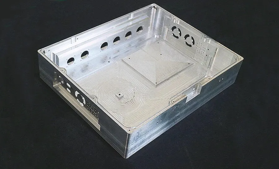
Combined with the specific deformable thin-walled parts to carry out a specific analysis, choose NX10.0 software to complete the parts processing design, determine the parameters of the parts, including wall thickness, depth, outer contour, surface roughness, etc., which in accordance with the length × width × thickness (100 mm × 100 mm × 30 mm) will be processed into a thin-walled parts of the quality of the standard, need to pay attention to the following points.
1. Rough machining technology
Considering that deformable thin-walled parts should be strictly controlled by the force factor, when rough machining, according to the sequence of cavity → outer contour processing, in the processing of the former, the outer contour will be unprocessed due to the bearing of large cutting force, combined with the processing standards of thin-walled parts, the nature of the parts and other factors, the use of software functions to set process parameters.
The diameter of the carbide milling cutter is 10 mm, arrange the cavity milling process, follow the parts to set the cutting mode of the toolpath, combined with the thin-walled parts in different areas of the depth of the difference, choose the corresponding way of cutting, such as radial cutting, helical cutting, parallel cutting, etc., in order to minimize the damage to the parts.
Take parallel cutting as an example, complete the cutting process with parallel tool walking mode, divided into unidirectional cutting, reciprocating cutting, and maintain a reasonable angle with the parts to improve the cutting quality.
The cutting process is as follows: click on “cutting parameters”, set the cutting route, cutting parameters and other data, according to the established data to complete the cutting process, leaving a margin of 0.1 mm at the bottom of the part to avoid over-cutting, thin-walled parts and other thicker parts can be appropriately increased depth of cut, to enhance the cutting effect.
Click on “non-cutting machining”, set the feed mode, related parameters, such as spiral feed mode, feed height, slope angle, etc., in addition to the spindle cutting speed, each feed and so on.
For external contour machining, the parameters remain unchanged and the tool remains unchanged. If the parameters must be changed due to changes in the external contour, click on “Cutting Parameters” again to extend or shorten the depth of cut, and set the number of tool paths and step spacing in finishing mode, so as to enhance the precision of step spacing machining and to reduce the cutting force to avoid the problem of deformation.
Click on “non-cutting movement” to realize the feed cutting of the closed area, select the type of feed, such as arc feed, set the radius of the feed, direction, etc., to reduce the cutting force and improve the qualification rate.
2, Semi-finishing technology
Semi-finishing machining can reduce surface errors in rough machining and improve machining quality, with contour machining as the main link in parameter setting. In internal contour machining, set the following process parameters: alloy end mill diameter of 8 mm, cavity milling process type, set the contouring toolpath cutting mode, constant step spacing, spacing of 0.2 mm, additional 3 cutters; constant public depth of cut per cutter, spacing of 2 mm.
Click on the key “Cutting parameters” and leave a margin of 0.05 mm on the side of the part.
Complete the machining work according to the following procedure: Click on “Non-cutting movement” to realize the feed cutting of the closed area, select the type of feed as slant feed, and set the parameters of the feed slope angle (0.5°) and height (0.5 mm);
To cut the open area of the part, set the parameters of the feeder arc angle (10°) and radius (5 mm). To ensure the smooth docking of the cutting modules, determine the location of the corner, indicated in the three-dimensional structure of the software, adjust the cutting speed and direction;
For external contour machining, the parameters and tools remain unchanged. If the parameters have to be changed due to changes in the external contour, click “Cutting Parameters” again to extend or shorten the depth of cut, set the feed mode and stabilize the cutting.
3. Finishing technology
Finishing is the last step in machining thin-walled parts. The finishing specification is directly related to the quality of the parts.
In this stage, machining focuses on the contour area. The process is combined with the system setup program to ensure precision.
Tool selection, machining process setup, and cutting mode configuration are essential steps. The step distance for each feed is set at 0.02 mm.
The depth of each cutter pass is set at 1 mm. These parameters can be adjusted based on different part positions.
Click “Feed rate and speed”, set the spindle speed and cutting feed according to the same parameters as those for roughing and semi-finishing;
Click on “Non-cutting movement”, select the feed mode in accordance with the characteristics of the closed area of the part, and set the feed parameters such as height (0.5 mm) and slope angle (0.5°).
For open-area cutting, select the feed type as arc feed, and set the arc angle (10°), radius (5 mm) and other relevant parameters.
When machining the outer contour, the parameters and tools remain unchanged. If the parameters have to be changed due to changes in the outer contour, click “Cutting Parameters” again to set the relevant values.
Processing difficulties and countermeasures
1. Easy deformation of concave cavity
When processing deformable thin-walled parts, the four walls of the concave cavity is extremely thin, if the fixture is not selected properly, it will form a pressure on the parts, so that the parts are deformed, and subsequent machining of the parts will be a major quality problem.
Need to strictly control the flat jaw clamping cavity strength, or the production of auxiliary support blocks, support blocks placed in the cavity, the formation of its support, the production of material selection of wood blocks, not too much width requirements, the length of the workpiece needs to be the same as the length of the concave cavity, in order to achieve a close connection.
In addition, in parts processing, also need to control the amount of each time the cavity is eaten into the right amount, if the amount is eaten into too much, will allow the tool to produce to the edge of the part pushed, aggravating the deformation.
2. Convex cavity thin-wall deformation
Convex cavity thin wall deformation occurs due to the top of the thin wall making contact with the iron block during clamping. This contact triggers deformation issues.
After clamping, tools such as a wooden hammer or rubber hammer can be used to tap the parts. This helps reduce the force on the parts and enhances the compactness between the parts and the pad iron.
In parts processing, it is essential to analyze the specific structural characteristics of the parts.
A practical approach is to increase the height of the thin-walled convex cavity. After milling, the excess part can be directly cut to control deformation.
Additionally, strict control of the tool’s cutting amount is necessary. The introduction of intelligent technology and human-computer interaction can enhance this control.
By integrating sensors and other hardware, CNC milling machines can better perceive the processing state at different stages. This enables the screening and convergence of machine tool processing data.
Artificial intelligence algorithms can be used to extract knowledge from data through aggregation and analysis.
The system can determine the deformation degree of the convex cavity with a thin wall and identify potential risk factors.
Based on this analysis, the tool cutting amount can be automatically adjusted. Adaptive control technology can optimize cutting parameters while considering various influencing factors.
Minimizing human intervention helps avoid similar deformation issues in concave cavities. Alternatively, a chip removal system can be installed. This system combines a chip removal chain plate with a chip removal trolley.
After machining, all waste chips are collected by the system and discharged into the chip removal trolley. This centralized collection makes it easier for workers to clean up.
3. Concave cavity is not easy for chip removal.
The concave cavity has a large residual capacity, and it is difficult to remove the chips after completing the residual capacity removal, which will aggravate the tool wear and lead to the problem of accumulated chip tumor.
In view of this situation, analyze the root cause of the concave cavity chip removal problem as a whole, formulate a relatively complete chip removal program, and introduce the “small knife running” machining process to reduce the negative interference it brings.
If the problem is still not solved, we can also try the following methods: cooling the tool, when the iron chips are machined out, by the impact of the coolant, play the role of chip removal;
Increase the feed volume to improve the chip removal and chip breaking effect; choose a more suitable chip-breaking drill bit, such as in the drill groove position arrangement of chip drilling knife, interrupting the chip, so that it is easier to remove.
Conclusion
In summary, this paper on the CNC milling machine easily deformed thin-walled parts processing launched a comprehensive discussion and analysis, the above proposed processing points in the implementation of the feasibility and effectiveness of strong, for the optimization of the overall processing process has a certain role in promoting.
However, it should be noted that the research in this paper still remains in the theoretical stage, need to combine with the actual conditions of the parts, adjust the processing details to improve the processing effect.