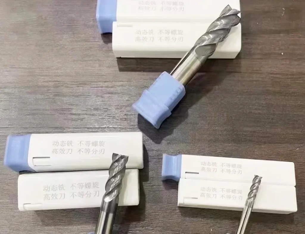
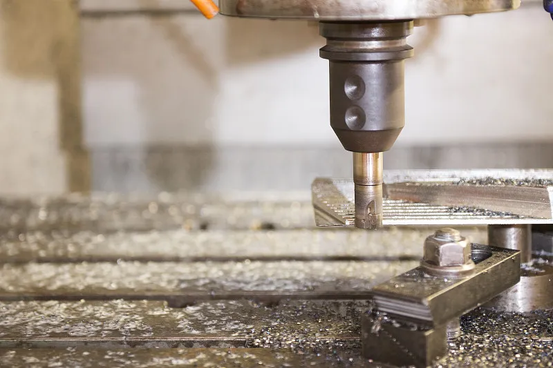
CNC tools are also called modern high-efficiency tools. Typical representatives are machine clamped indexable carbide tools as mainstream products and super-hard tools (diamond, cubic boron nitride tools) under development.
CNC tools are actually the product of standardization, to meet the requirements of CNC machine tools automatic tool change. CNC tools are generally not sharpened, even if you want to carry out tool resharpening coating, but also the use of outsourcing.
Characteristics of modern high-efficiency cutting tools
Modern high-efficiency cutting tools are designed to achieve high efficiency, high precision, and high reliability.
Tool manufacturers have shifted from simply “selling knives” to providing complete high-efficiency machining solutions based on processing characteristics and workpieces, marking a major strategic change in the tool industry.
Customers can not only choose the right tool from the tool samples but also obtain an overall cutting and processing solution from tool manufacturers.
Tool manufacturers provide metal cutting experiments for each type of insert, offering customers reference values for cutting dosage, and the tool samples can also be used as a cutting manual.
CNC technology program and tool selection
Traditional process regulations heavy process flow, process, tool handling is simple, just write it out on the line.
For example, “75 ° external turning tool”. But the CNC tool is a standardized product, to the tool manufacturer or the market to buy, you must choose the appropriate machine tool system specifications of the corresponding standard toolholder.
And inserts and shanks to match, or tool and shank to match.
All tools are pre-loaded in the tool magazine, through the CNC program selection and tool change instructions for the corresponding tool change action.
Automatic tool changer can quickly and accurately install the tool on the machine spindle or return to the tool magazine.
The CNC process regulations include not only the process flow but also the requirement to equip a tool card.
This card should provide information such as the tool number, tool patch, blade shank, and tool shank model specifications.
Description of the part of the tool processing, it is best to attach a tool diagram, it is more intuitive. This introduces a new process task – tool selection.
Select the tool that meets the process requirements from the tool manufacturer’s samples, do the tool card, tool library management.
New and efficient tools and process changes
With the continuous development of CNC tool technology, a large number of new high-efficiency tools have emerged, resulting in great changes in metal cutting process protocols.
For example, modern enterprises in order to improve productivity, have begun to take measures to reduce or merge processing procedures.
Including roughing directly after finishing, eliminating semi-finishing; rough boring directly after finishing;
Fine reaming after drilling in one place; face rough milling after a finish milling to meet the requirements.
This means that roughing should try to remove the machining allowance, finishing should ensure that the processing parameters and quality meet the requirements.
This undoubtedly puts forward higher requirements for machine tools and cutting tools, prompting changes in the process.
It can be said that the machine tools, cutting tools to change the process regulations.
Modern enterprises are also promoting the use of new tools, such as gear shaving cutters (for processing internal gears), gun drilling (for drilling deep holes), ball cutters (for milling surfaces), thread cyclone milling (with a lathe to process threads), thread milling cutters (for milling threads in the machining center, offering high efficiency and precision), and maize milling cutters (for roughing, more durable than end milling cutters).
These new tools directly lead to the development of new processes.
Impact of CNC tools on CNC machining process
The following practical production cases illustrate the impact of CNC tooling on the CNC machining process.
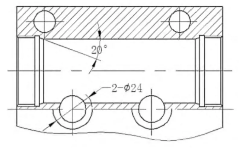
Figure 1 shows the valve body parts structure, and this group of holes in the structure presents five problems that need to be solved.
First, how to cut the ring-shaped groove?
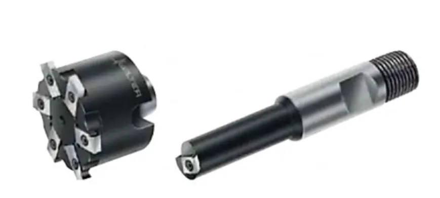
Ring-shaped groove processing uses a ring groove milling cutter, similar to the internal groove lathe, as shown in Figure 2.
The cutter is selected based on the ring groove’s diameter and width, and the shank used is the flattening cutter shank BT40-SLN.
Secondly, how to rough and finish milling 20° short internal taper?
The solution is interpolation milling, offering flexible tool selection.
You can choose from ball milling cutters, helical interpolation milling cutters, fillet milling cutters, etc., with shanks such as the flattening cutter shank BT40-SLA or the cylindrical straight shank BT40-ER.
Third, rough and fine boring of the inner hole
The key is tool selection, rough boring head selection RBH32-42-C, fine boring head selection CBH25-47, shank BT40-LBK.
Fourth, Threading
Thread milling processing has become very common in modern enterprises.
The benefits of thread milling include high efficiency, less burr, and the ability to select a corresponding thread milling cutter based on the nominal size of the thread and pitch.
The shank is mostly a flat shank BT40-SLA.
Thread milling cutter type
Thread milling cutter has clamped indexable insert milling cutter and the whole carbide milling cutter.
Carbide indexable milling cutters with indexable inserts allow the thread milling cutter to be freely converted between external and internal threading to meet the requirements of various threading standards.
These thread milling cutters are often equipped with internal coolant holes to allow coolant to reach the cutting zone efficiently.
Versatility of thread milling
Thread milling offers excellent versatility, as only one multi-tooth thread milling cutter is needed to produce threads with the same pitch in different hole diameters;
Single-ended thread milling cutters with a universal profile can also be used for threads with different standards, such as ISO metric threads and American threads.
Thread milling is an effective solution to problems such as tool bending, wear, and the “elasticity” of the material being machined.
The main difficulty in the tapping process is chip removal, as long chips can clog the tap’s chip chute, leading to tap breakage and potential part scrapping.
However, in thread milling, efficient chip removal is achieved without difficulty.
While most taps are not suitable for machining hardened materials, solid carbide thread milling cutters are suitable for threading hardened materials;
The formability of taps means that they can only be used for threads of specific diameters and pitches.
Thread milling
Thread milling can also be done with a thread cyclone. Cyclone milling is a high-speed thread milling device used in conjunction with precision lathes.
It is a method of milling threads from the workpiece by using a carbide molding cutter mounted on a high-speed rotating cutter plate.
Because of its high milling speed (speed up to 400m/min), processing efficiency, and the use of compressed air for chip cooling.
It is named after the cutting splash like a whirlwind during the machining process, as shown in Fig. 3.
It is very suitable for machining threaded products such as worm gears and screws. One cut molding, no need to retreat slot, good interchangeability.
However, cyclone milling will make the small diameter workpiece has a large deformation (large diameter parts deformation is smaller), but can be solved by the screw correction.
Cyclone milling in the machining process needs to complete five machining movements:
The cutter plate drives the carbide forming cutter to rotate at high speed as the main motion, while the lathe spindle rotates the workpiece at a slow speed as an auxiliary motion.
Cyclone milling follows the pitch or lead of the workpiece for axial feed motion, moves radially under the lathe’s drag plate for cutting motion, and has a helical angle adjustment for rotary motion within a certain range.
Fifth, countersinking
The 2-¢24 features countersinking holes, traditionally processed using countersinking drilling with a guide column.
However, in CNC machining, the use of countersinking drills and reaming tools is decreasing, while vertical milling cutters with interpolation milling are becoming more common, aligning with modern CNC machining trends.
As shown in Figure 4 countersinking processing.
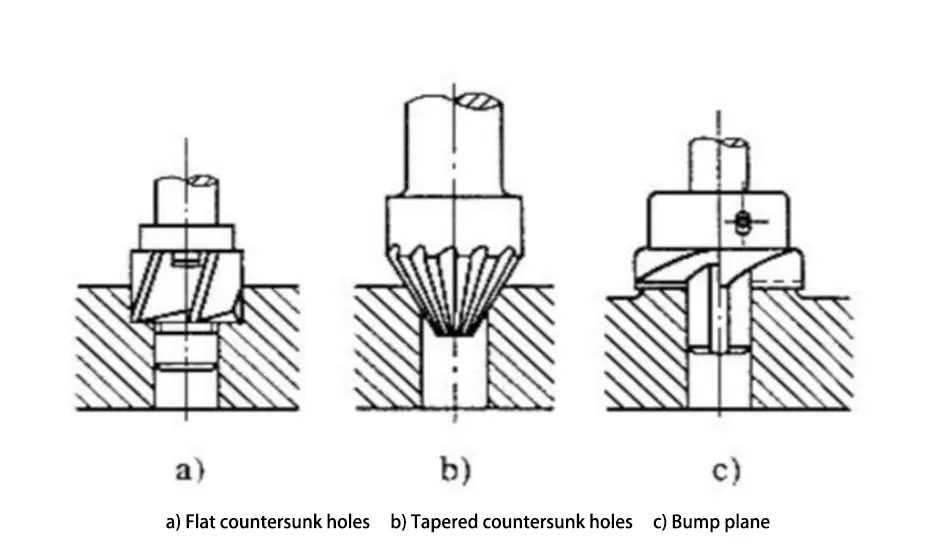
Countersink drilling processing surface is small, the basic use of molding processing tools.
Cutting edge is long, easy to produce vibration. Profile face hole has a certain relative position (coaxiality, perpendicularity, etc.) and shape (flatness, contour, etc.) requirements.
Dimensional accuracy is often not required, mainly for screws, rivets and other connectors to maintain a reliable connection needs.
The profile depends on the shape of the connector end.
In CNC machining, the forming process of countersinking is not common.
More often, it is achieved through programming and milling methods.
In Figure 4(a), cylindrical countersinking is processed using a flat-bottom milling cutter, which completes the operation through programmed milling.
(c) In Fig. 4, the flat surface machining of a convex table can be realized by the milling process with vertical milling cutters;
(b) Tapered countersinking in Figure 4 can be considered as countersinking with special tapered countersinking drills.
However, CNC machining can also be carried out by programmed methods with chamfering milling cutter milling process.
Generally small-sized holes are directly countersinking with integral taper countersinking drills, while large-sized holes are milled with programmed trajectories.
In fact, 90° taper countersinks are also commonly used for deburring chamfers, i.e. chamfers are milled by programmed track milling.
As with the drilling tools, the shanks of the countersinks are, wherever possible, of the cylindrical straight shank type, as the Morse taper shank type offers poor clamping reliability.
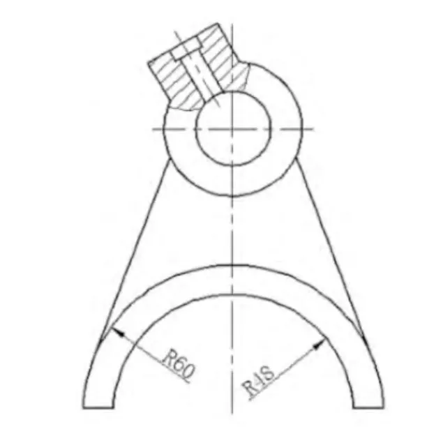
The fork foot shown in Figure 5 is a semi-circular arc with a width of 12 mm. An end mill with an endface flute can be used to mill the fork foot plane by circular interpolation;
The center groove of the square tool holder shown in Fig. 6, because the center groove has an R3 fillet, it can be milled with an R3 fillet milling cutter; the center groove can be milled with an R3 fillet milling cutter.
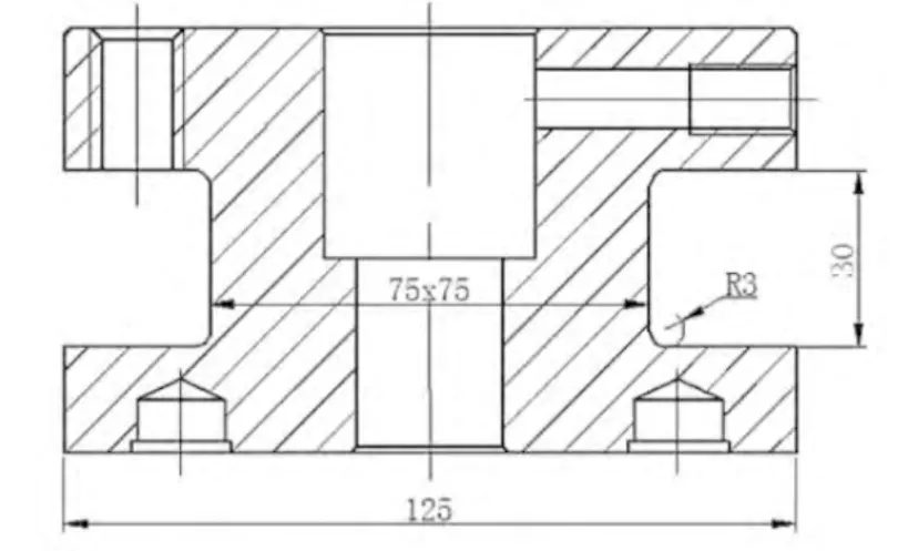
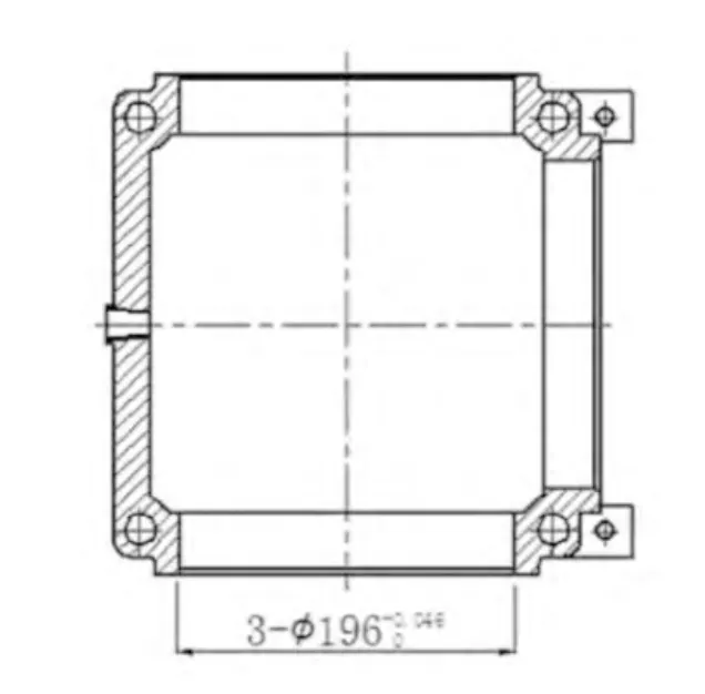
Figure 7 shows box parts with three ¢196H7 precision holes.
Traditionally, these holes are bored one by one using a boring die, but on a horizontal machining center, a rotary table head can be used for rough and fine boring to ensure machining accuracy and surface quality.
Additionally, for ¢196 orifice chamfering, a chamfering milling cutter can perform chamfering using arc interpolation milling.
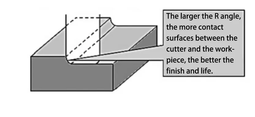
Milling surfaces generally use a round corner milling cutter for roughing and a ball milling cutter for finishing.
The round corner milling cutter improves processing efficiency, as both the bottom and side edges can be used for plane processing, enhancing the surface machining quality of the workpiece.
The larger the R angle, the more edge contact with the workpiece, resulting in better surface machining quality, as shown in Figure 8.
Machining method for starting cutting of internal groove (cavity)
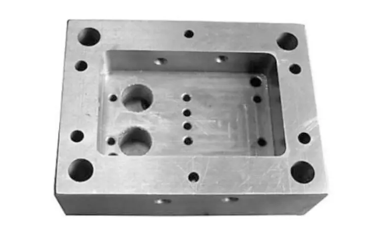
Figure 9 shows the inner groove (cavity) processing, where the main difficulty lies in the starting cutting methods.
Generally, there are four methods to choose from, one of which is to pre-drill the starting groove (cavity).
One is the pre-drilling of the starting hole method.
The pre-drilling start hole method begins by drilling a hole in the solid material that is larger than the milling cutter’s diameter.
The milling cutter then enters the hole and uses the line cut method, ring cut method, or a combination of both to mill out the inner groove (cavity).
Generally, this method is not used, because with this method, the drill tip pit will remain in the inner groove (cavity), and another milling method is needed to mill away the drill tip pit and add a drill;
In addition, the milling cutter through the pre-drilled holes due to sudden changes in cutting force generated by the vibration, often resulting in damage to the milling cutter.
The second is the insert milling method.
Insertion milling method, also known as Z-axis milling method or axial milling method, is the use of the front face of the milling cutter for vertical downward cutting processing methods.
When using this method to start cutting the inner groove (cavity), the end of the milling cutter must have a cutting edge that extends over the center of the cutter.
The end face edge is mainly used to process the bottom plane perpendicular to the side, and the cutting feed rate should be slower at the start.
After the milling cutter cuts into the surface of the workpiece, then gradually increase the cutting feed rate.
Otherwise, it is easy to damage the milling cutter when you start cutting the inner groove (cavity).
The insert milling method is suitable when the processing task requires a tool with a larger axial length, such as milling large cavities or deep grooves.
Because this method effectively reduces the radial cutting force, it offers higher machining stability compared to side milling.
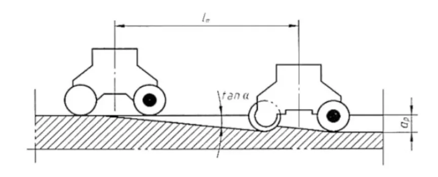
Third is the ramp milling method.
The slope walking milling method is one of the best ways to start cutting the inner groove (cavity).
It is a cutting method that uses X, Y, and Z three-axis linkage linear slope walking to lower the cutter and achieve the full axial depth, as shown in Figure 9.
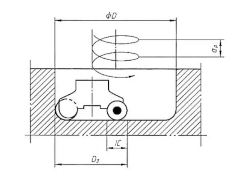
Fourth is spiral interpolation milling.
Spiral interpolation milling is the best method to start cutting the inner groove (cavity).
It is a machining method that adopts X, Y, Z three-axis linkage, and cuts the inner groove (cavity) in the form of helical interpolation, as shown in Fig. 10.
Spiral interpolation milling is a very good method to start cutting the inner groove (cavity).
The surface roughness Ra value of the cut internal groove (cavity) is small and the surface is smooth.
The cutting force is small, the tool durability is high, and only a small starting cutting space is required.
Conclusion
CNC machining tools directly affect the machining efficiency, accuracy, surface quality and stability.
High-performance tools can increase cutting speed, reduce errors, and adapt to the processing needs of different materials.
Reasonable tool selection and optimization can improve chip removal performance, extend tool life, reduce costs and improve productivity.
Therefore, the rational application of tools is crucial to CNC machining.

